




iScope Data Visualization and Analysis Software: How HuazhongCNC Predicts Five-Axis Machining Results Before the First Cut
Key Takeaways
- iScope is Huazhongcnc’s self-developed instruction-domain data visualization and analysis software for five-axis linkage machining.
- It replaces costly trial cutting with data-driven prediction, letting engineers forecast machining results and diagnose defects before — not after — production.
- iScope fuses three data sources into one 3D view: .dat interpolation data, .NC/.ptp G-code trajectories, and .stl 3D models.
- Built-in analysis tools (chromatogram marking, waveform-to-3D synchronization) allow one-click, precise root-cause tracing of machining defects.
- Real-world cases show iScope resolving singularity-zone burn marks and impeller tool-mark defects, cutting quadrant reversal error to as low as 0.1 μm.
The Problem: Five-Axis Machining Still Relies on Trial and Error
In five-axis linkage machining, the traditional workflow has always depended on actual trial cutting to verify results. This approach is slow and expensive: it wastes raw material, consumes valuable machine time, and makes defects difficult to predict in advance. These pain points don’t just reduce production efficiency — they also cap how far machining accuracy can improve, because problems are only visible after the part has already been cut.
Huazhongcnc’s self-developed iScope instruction-domain data visualization and analysis software was built to break this cycle. By shifting the process toward “data prediction,” iScope reshapes five-axis debugging logic: engineers can accurately forecast machining results and analyze defects in depth without a single trial cut. Five-axis machining moves from after-the-fact remediation to pre-judgment before machining and analysis during machining.
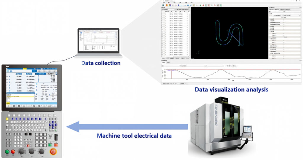
What Is iScope? Core Functions of Huazhongcnc’s Five-Axis Analysis Tool
1. Accurate Parameter Matching for a True Digital Replica of the Machining Process
iScope’s foundation is precision at the parameter level:
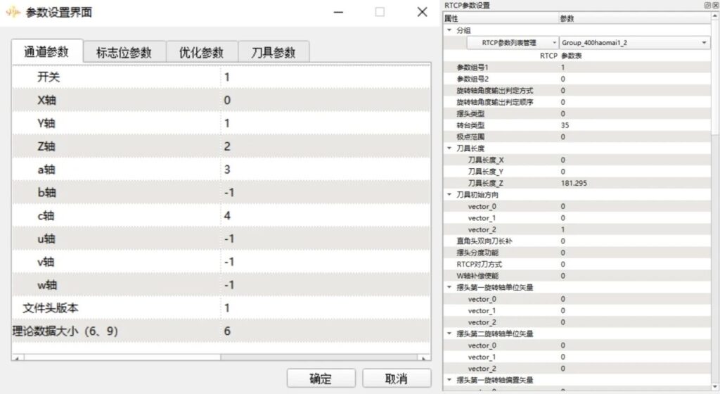
- Axis parameter configuration matches the channel parameter settings of the actual machine tool exactly.
- RTCP parameters, tool information, and workpiece coordinate system data are entered with full accuracy.
Full-parameter synchronization means iScope faithfully reconstructs real machining conditions, giving engineers a reliable data foundation for everything downstream: trajectory display, defect localization, and precision analysis.
2. Multi-Source Data Fusion with 3D Visualization
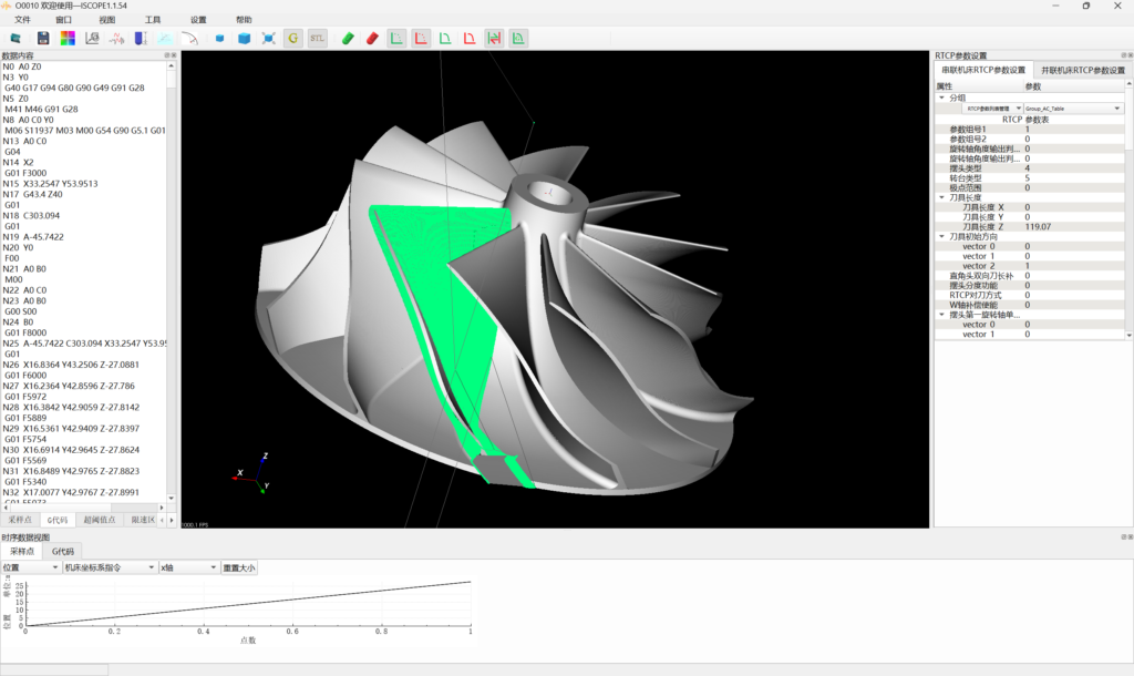
iScope supports importing multiple data types and fusing them into a single, deeply integrated 3D visualization of the model, the programmed trajectory, and the actual machining interpolation data:
- .dat interpolation data — Collected via HCNC Group’s self-developed SSTT debugging and diagnostic tool, which captures system commands and actual machine tool positions. iScope parses this data to display the 3D trajectory and sampling points, along with time-domain curves for velocity, acceleration, current, following error, and contour error.
- .NC / .ptp machining G-code — Displays the programmed trajectory in 3D, giving engineers an intuitive view of tool-path planning before it ever reaches the machine.
- .stl 3D models — Loads a 3D reference view that can be overlaid against the programmed trajectory and the actual interpolation trajectory, so engineers can precisely evaluate the fit between them and quickly pinpoint the root cause of any defect.
3. User-Friendly Interaction with Precise Defect Traceability
Intuitive, low-barrier design:
- 3D view interaction follows conventions engineers already know from common software, so there’s no learning curve.
- Data display supports on-demand toggling and coordinate system switching, helping users focus quickly on the information that matters.
- Analysis tools are highly integrated — chromatogram marking, fluctuation identification, and other specialized operations complete in a single click.
- View reset and project-save functions mean work states are always recoverable and analysis can continue where it left off.
Precise feature data traceability:
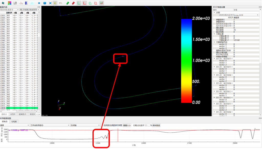
Engineers can color-code a chromatogram by data range to instantly locate abnormal zones. Double-clicking an anomaly on the waveform graph simultaneously marks the corresponding point in both the 3D view and the sampling point view — precisely matching the defect location to its data source. This turns defect diagnosis from experience-based guesswork into a targeted, evidence-based process.
iScope in Action: Two Real-World Five-Axis Defect Cases
Case Study: Resolving a Singularity Zone Burn Mark
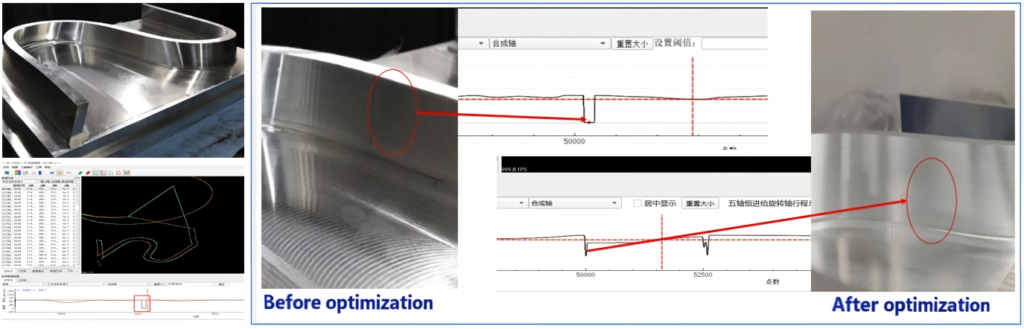
Before delivery, a machine tool showed a blackened, burned singularity zone on an S-shaped test piece. Using idle-run sampling and iScope analysis, engineers found the synthesized speed in the singularity zone was near zero — the root cause of the burning. By changing the programming and post-processing approach and adopting the G94.6 function, the singularity zone burning issue was fully resolved.
Case Study: Eliminating Impeller Flow-Channel Tool Marks
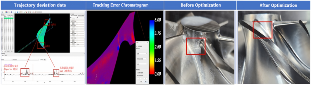
A customer reported tool-mark defects in the flow channel of an impeller part. iScope analysis quickly identified the cause: a sudden reversal jump on the Z and A axes. By optimizing axis roundness compensation and servo parameters, engineers reduced the quadrant reversal jump value to just 0.1 μm, completely eliminating the tool-mark defect and achieving the required machining quality on the first attempt.
Why It Matters: From Trial-and-Error to Data-Driven Precision
Traditional five-axis machining is locked into a repetitive, resource-intensive cycle: machine the part, discover a defect, adjust parameters, cut again. iScope’s data visualization and analysis capabilities break that cycle. Because machining results can be predicted without a physical trial cut, debugging cycles shorten significantly and machining efficiency improves. Precise management of RTCP and axis parameters further guarantees trajectory accuracy — giving five-axis machining a double layer of assurance on both precision and stability.
From trial-cutting verification to data prediction, and from experience-based analysis to precise traceability, HCNC Group’s iScope is using rigorous data analysis to solve the long-standing pain points of five-axis machining — supporting high-precision, high-efficiency production of complex curved-surface parts.
Frequently Asked Questions
What is iScope used for?
iScope is HCNC Group’s instruction-domain data visualization and analysis software for five-axis linkage machining. It predicts machining results and diagnoses defects using real machine data, without requiring an actual trial cut.
What file types does iScope support?
iScope imports three data types for fused 3D visualization: .dat interpolation data (captured via HCNC Group’s SSTT debugging tool), .NC/.ptp G-code files for programmed trajectories, and .stl files for 3D model overlays.
Does iScope eliminate the need for trial cutting entirely?
iScope is designed to predict machining outcomes and catch defects before production, significantly reducing reliance on physical trial cuts. This shortens debugging cycles and lowers material and time costs associated with traditional test-cut verification.
How does iScope help trace the root cause of a machining defect?
Engineers can color-code data ranges on a chromatogram to spot abnormal zones, then double-click anomalies on the waveform graph. iScope simultaneously marks the corresponding point in the 3D trajectory view and the sampling point view, linking the defect directly to its underlying data source.
What results has iScope delivered in real production cases?
In documented cases, iScope helped resolve a singularity-zone burn defect on an S-shaped test piece and reduced quadrant reversal error to 0.1 μm on an impeller part, eliminating tool-mark defects and achieving required quality on the first machining attempt.

